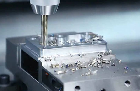
The process of invention and design development is one that we enjoy. As we can see, concepts are being combined in new ways. We finally arrive at a design that is perfect in every way, both technically and aesthetically, after many iterations of prototyping and experimentation. But do you know what would be even better? Take a look at your design in its entirety.
However, while the design is attractive and functional, this is only half of the battle. Designing plastic parts for injection molding is necessary for the majority of plastic parts because injection molding is the most common low-cost technology for producing large numbers of plastic parts.(While cnc turning parts are rarely milled for very special geometric structures, the cost of each part is typically 50-100 times higher than the cost of cnc milling parts. This has its own set of requirements that must be met. With the help of the following design guidelines, you can keep your mold costs low while maintaining the aesthetic appeal of your design.
But, before we get into the specifics of how to adjust the 3D printing design prior to injection molding, let's take a look at the manufacturing process itself first. What is the procedure for injection molding?
The Fundamentals of Injection Molding
It is very simple at its most basic level: two large metal mold halves are joined together, plastic or rubber material is injected into the cavity formed by them, everything is allowed to cool, the parts are ejected, and the two mold halves are separated simultaneously.
In fact, it is possible that things will become more complicated. Although the plastic materials used in injection molding are melted, they are not actually heated because the material is pressed into the injection port by means of a large auger, which is a mechanical device. Compressing and heating the material causes it to heat up and begin to flow into the mold.
The mold itself must be the inverse of the molded part, and the geometry can become quite complicated as a result of this requirement for negative geometry. You can see how the inside of the cup is formed by the geometry of one half of the mold, while the outside of the cup is formed by the other half of the mold if you examine a very simple red cup, such as the one in which we used to play beer ping-pong when we were in college. This is very simple because you already have a large cone that extends from one side to the other on your hands.
Molds become increasingly complex as the shapes being produced become more and more complex. Instead of the traditional red coffee cup, consider a simple plastic coffee cup. The handle is made from two different molds: one for the inside and brass cnc machining another for the outside. But what about the handle?
It is necessary to use action in the mold when two molds cannot form part geometry in a straight line. This action can be either sliding or screwing. Using the mold's action, very complex shapes, such as the threads of nuts and screws, can be formed, including the threads of nuts and screws. However, this adaptability comes at a cost: the cost of a simple straight-pull mold versus an action mold is typically ten times higher in comparison.
Prepare your design so that it will be simple to mold.
The most important rule to follow when attempting to reduce mold processing costs is to avoid undercutting. When a part of a geometric body is under another part, when a certain part of the geometric body cannot be formed by a half mold, or when a part of the geometric body becomes stuck in the mold, the term "undercut" is used. Take, for example, a commonly used feature: the snap fit. In this case, a simple injection mold cannot be used to mold the buckle on the left because the underside of the buckle cannot be touched from the bottom and the other part of the housing is completely blocked by the buckle itself. For this problem, we can easily solve it by cutting a small piece of material from the case, as shown in the picture on the right, and then forming the buckle around it.
The design is often evaluated in the context of a glass table with one beam of light shining from below and another beam of light shining from above, which is a common image in our minds. In a situation where the light touches every surface on a workpiece, it is easy to shape; in the event that there is a shadowed area, it is an undercut.
During the molding process, another factor to consider is how easy it will be to remove the part from the mold once it has cooled and the mold has separated from the part. Some geometric shapes make it difficult to demold parts, make molding difficult, increase cycle time, and ultimately raise the cost of each individual part by a significant amount.
If the straight edges on the part are in the same direction aluminum cnc machining service as the die stretch, you should try to avoid adding a small amount of draft or taper to the part whenever possible. Making the part slightly tapered, as in the case of the red cup, can make it easier to remove from the mold when it is hot. When it comes to aesthetics, a 1 to 2 degree taper, which is almost insignificant, can be used. However, when it comes to draft angle, the length of the straight side determines how much of a draft angle is used. The greater the demand, the higher the price.
Sharp corners, on the other hand, have a tendency to become stuck in the mold, so you should round the corners of the molded part on all sides. If the corner also serves as a parting line, this is an exception because the sharpness of the corner can be maintained because it is formed by two different parts of the mold. Between injection and spraying, there is cooling, which influences the geometry of the part even more. Once the cavity has been completely filled, the part will begin to cool at a rapid rate. The cooling process begins from the outside in, resulting in the formation of a skin on the material almost immediately. When the part cools, it contracts in size. If the thickness of all areas on the part is the same, the part will shrink uniformly and look good when it is ejected from the mold.
As opposed to this, if a part has some extremely thick areas and some extremely thin areas, the thin areas will cool and harden first, while the thick areas continue to cool. In this case, because the thin area surrounding the geometry has cooled and a skin has formed on the surface of this part, when the melting center is forced to cnc machining cool and shrink, it will draw the curved surface down, causing depression marks on the smooth surface of the part and causing it to lose its attraction force.
In order to avoid dent marks, please ensure that the thickness of the material is relatively uniform throughout the part, that the ratio between the thin and thick sections does not exceed 2:3, and that the transition from the thin to the thick section does not occur abruptly between the thin and thick sections. To conclude, when designing the part, try to visualize which surfaces will be formed by the upper mold half, which surfaces will be formed by the lower mold half, and the exact position of the parting line when the upper and lower mold halves come together. Although it takes some practice to become proficient at this, it greatly simplifies the molding process.


